


TECHO ELECTRICAL & MECHANICAL
BLOG
Jan 15,2026
How to Read Pump Curves: Complete Guide to Flow, Head & NPSH
Master pump selection with our complete guide to flow rate, total dynamic head, NPSH, efficiency & affinity laws. Learn to read pump curves & avoid cavitation. Get free expert advice from TITECHO engineers today!

This guide introduces six pump parameters commonly reviewed during pump selection, operation and maintenance. It is intended to help readers prepare the information needed for a technical discussion, including the required duty point, liquid properties, installation arrangement and applicable documentation. The content is a general overview only; pump selection, safety, compliance and operating decisions should be confirmed against the specific product data, system design and site conditions.
1. Flow Rate (Q) — Understanding Required Liquid Volume

Flow rate describes the volume of liquid moved in a stated period of time. It is one of the inputs used to determine whether a selected pump and system arrangement are suitable for the required duty point.
Lower than required → may result in insufficient supply for the intended process
Higher than required → may alter system behavior and can increase energy or control requirements
Common Units
• GPM (Gallons Per Minute) — often used in residential and light-commercial contexts
• m³/h (Cubic Meters per Hour) — often used in industrial and larger systems
• L/s (Liters per Second) — used in a range of smaller or specified applications
Application Considerations
In a dishwashing line, the required flow should be considered together with the rinse process and the rest of the system. In a well or booster installation, frequent cycling may warrant a review of the demand profile, controls, storage or selected equipment. The appropriate response depends on the complete system arrangement rather than on flow rate alone.
Selection Consideration
Identify the expected demand profile, including average demand, peak demand, simultaneous use and foreseeable operating changes. Any capacity allowance should be justified by the application and checked against the pump curve, system curve and control arrangement. For industrial applications, the requested duty point and any calibration or testing needs should be agreed for the specific project.
2. Head (Total Dynamic Head) — Evaluating System Resistance

Head is used to express the energy a pump must provide to overcome elevation and resistance in a system. It is normally stated as a height, while any pressure equivalent depends on the liquid and the reference conditions. The required head should be calculated for the actual installation.
Units & Conversion
• Head may be stated in feet (ft) or meters (m)
• Conversion to pressure should use the relevant liquid density and stated reference conditions
Two Useful Terms
• Static Head — elevation difference between the relevant liquid levels when there is no flow
• Total Dynamic Head (TDH) — the head requirement after considering static head and system losses from piping, valves, bends, fittings and other components
Selection Consideration
A vertical lift alone does not define the required TDH. Piping length, diameter, roughness, fittings, valves, flow rate and liquid properties can affect the system calculation. Use the full system layout and the relevant pump curve when evaluating the duty point. Technical calculation support, if available, and its scope should be confirmed with the selected supplier or project engineering team.
3. Power Consumption & Efficiency — Assessing Operating Inputs
Review the relevant power values for the selected motor-and-pump arrangement:
• Input Power — electrical power supplied to the motor or drive, as defined in the relevant product documentation
• Hydraulic Power — useful energy transferred to the liquid at the specified duty point
• The method used to calculate power and efficiency should match the selected product, liquid, controls and test basis
Efficiency compares useful hydraulic output with the relevant power input. It changes with pump design, duty point, liquid properties, motor and drive configuration, and operating conditions. The applicable efficiency values and test conditions should be taken from the specific product documentation rather than assumed from a general range.
Why It Matters
Operating cost depends on measured or specified power consumption, operating hours, demand variation, local electricity price, maintenance practices and the system duty point. When comparing options, estimate energy and lifecycle effects using the relevant performance curves, load profile and clearly stated assumptions.
Evaluation Note
Where an efficiency classification, energy label or high-efficiency motor is relevant, confirm its availability, test basis, documentation and applicability for the selected model and market. Any energy-cost or payback assessment should use the confirmed duty point, operating schedule, tariff and project assumptions; results are not a default product outcome.
4. NPSH (Net Positive Suction Head) — Managing Cavitation Risk
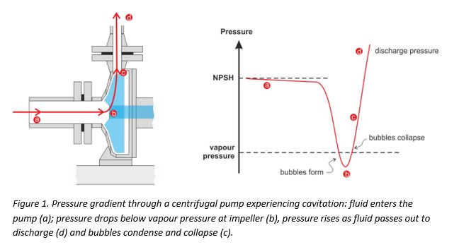
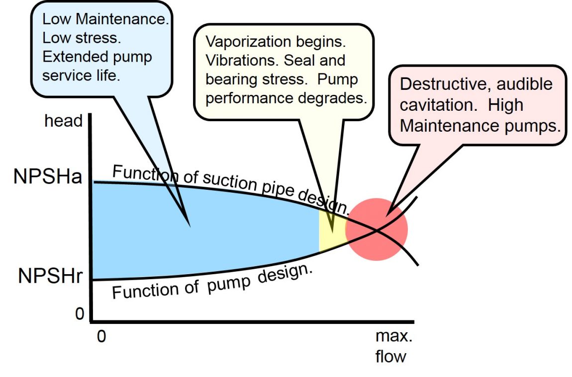
Cavitation can occur when local pressure in the suction region falls below conditions associated with vapor formation. It may contribute to noise, vibration, reduced performance or damage, depending on the pump, liquid and operating conditions. Suction-system design should therefore be assessed during selection and operation.
Key Values
• NPSHr — the required NPSH stated for a particular pump, speed and duty point in the relevant manufacturer curve or documentation
• NPSHa — the NPSH available from the system calculation, considering atmospheric conditions, liquid vapor pressure, elevation and suction-side losses
Design Consideration
Assess NPSHa against the applicable NPSHr for the selected pump and duty point, with a margin determined by the manufacturer’s documentation, the liquid, operating range, installation conditions and relevant engineering practice. Do not apply a generic numerical margin or NPSHr target without confirming the project basis.
Possible Design Measures
• Review suction-line length, diameter and layout to limit avoidable losses
• Review the relative elevation of the pump and liquid source where the installation permits
• Review unnecessary restrictions, valves, bends or strainers as part of the hydraulic layout; changes should be assessed by qualified personnel against the complete system design
5. Speed (RPM) & Affinity Laws — Variable-Speed Considerations

For centrifugal pumps, changes in impeller speed can affect the duty point. Under the conditions for which the affinity relationships are applicable, the following relationships may be used as an initial estimate and should be checked against the pump curve:
• Flow varies approximately with RPM
• Head varies approximately with RPM²
• Power varies approximately with RPM³
Practical Consideration
A variable-frequency drive (VFD) may be considered where the equipment and control strategy are suitable for variable-speed operation. Any change in speed can affect flow, head, power, NPSH conditions, motor cooling and system behavior. Expected energy results should be calculated from the selected pump curve, control profile and actual operating conditions.
Operating Limit Note
Do not operate beyond the documented speed limits for the specific pump, motor and drive arrangement. Before using a VFD, confirm the approved speed range, motor insulation and cooling, control settings, mechanical limits, warranty conditions and any required accessories with the relevant product documentation and supplier.
6. Fluid Compatibility — Review Pump Materials Against the Liquid

Liquid properties can affect pump performance, material selection, sealing arrangement and maintenance requirements. Compatibility should be reviewed for the actual liquid, concentration, temperature, solids content and operating conditions; a material suitable for one duty is not necessarily suitable for another.
Key Fluid Properties to Evaluate
• Specific Gravity — may affect the hydraulic power and motor-sizing assessment
• Viscosity — can alter flow, efficiency, power demand and the suitability of a pump type
• Corrosiveness / Abrasiveness / Toxicity — can influence the required wetted materials, seals, containment and safety measures
Material-Selection Review
• Material options, which may include stainless-steel grades, duplex or nickel alloys, and lined constructions, should be evaluated only against the specified liquid and service conditions
• The chemical, mechanical, temperature, pressure and safety requirements should determine whether a particular material or lining is appropriate
• Material names or grades in a general guide do not establish compatibility for a specific liquid or process
• Final material and seal selection requires a documented compatibility review for the exact liquid and service conditions
Selection Reminder
Do not select a pump designed for a water-service duty solely on the basis of flow and head when the liquid is chemical, viscous, abrasive, flammable or otherwise demanding. Provide the liquid name, concentration, temperature, solids information, pressure, operating cycle and safety requirements so that the wetted parts, sealing and containment approach can be reviewed for the intended service.
How to Read & Use a Pump Performance Curve
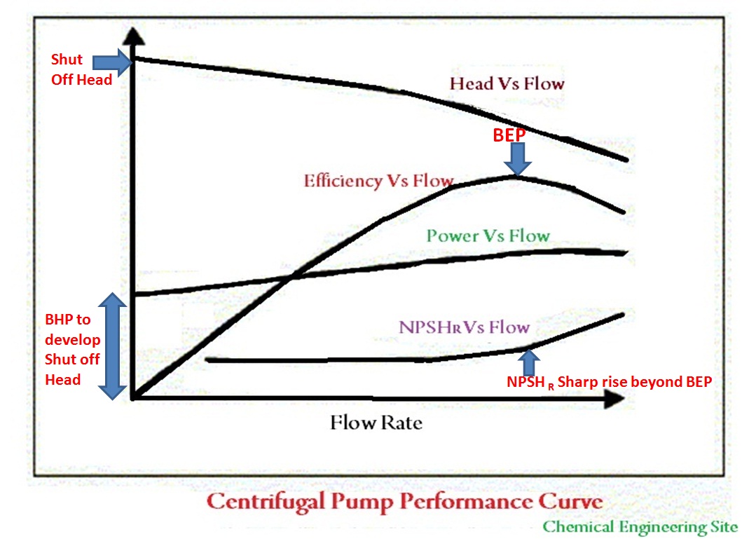
When available for the selected product, a pump performance curve is a key reference for comparing the required duty point with the pump’s stated flow, head, efficiency, power and NPSH characteristics. Review the curve version, pump configuration, speed, impeller diameter, liquid basis and test conditions before relying on it.
• X-axis: Flow rate
• Y-axis: Head
• Additional curves may include efficiency, power and NPSHr
Selection Practice
Use the relevant product curve together with the calculated system curve and the manufacturer’s stated operating guidance. The best-efficiency point (BEP) is curve-specific and should not be treated as a fixed percentage range. Operation away from a recommended region may affect energy use, vibration, reliability or operating stability, so the acceptable operating range should be confirmed for the particular pump and application.
Quick Pump Selection Checklist
Before purchasing or requesting a technical proposal, assemble the following information for the intended application:
• [ ] Required flow rate, including average demand, peak demand and any capacity allowance justified by the demand profile
• [ ] Total dynamic head, including relevant losses from pipes, fittings, valves and equipment
• [ ] Full liquid properties, including specific gravity, viscosity, corrosiveness, solids content and temperature
• [ ] Energy budget and any applicable energy-efficiency objectives or motor requirements
• [ ] NPSH assessment and the design margin appropriate to the selected product, liquid and installation
• [ ] Applicable target-market standards, certifications, markings and documentation requirements
• [ ] Voltage, frequency, control and installation compatibility requirements
This information supports a more informed comparison of pump options and helps identify items requiring engineering review. Final selection should be based on the confirmed product data, system calculation, project requirements, applicable documentation and order confirmation.
Discuss Application-Specific Pump Requirements
Share the required flow, head, liquid information, operating conditions, electrical supply, control needs and target-market documentation requirements to help structure an initial technical discussion. Product options, the scope of any calculation assistance, service scope and quotation details should be confirmed for the particular project.
Related News
LATEST
INFORMATION
Get the latest product information of the company
NAVIGATION
PRODUCTS
CONTACT US
Telephone: +86 13305761511
Email: info@cntecho.com
Add: RM. 602, BUILDING B, NO.1551 SHUANGSHUI RD., LUQIAO DIST., TAIZHOU CITY, ZHEJIANG, CHINA

Copyright © 2026 TECHO ELECTRICAL & MECHANICAL (TAIZHOU) CO., LTD. All Rights Reserved.